200 W/cm²
Cold plate heat flux · C-HH-01
≥ 3,000 W/m·K
Vapor chamber conductivity · C-HH-03
35 MPa
Pipeline working pressure · C-HH-06
C5-M
Marine corrosion grade · C-HH-04
Series C-HH
Every part of the loop, from the plate to the pipe.
Aluminum, copper, titanium or stainless construction — vacuum brazed, friction-stir welded or built with embedded copper tube, chosen for your heat load and envelope.
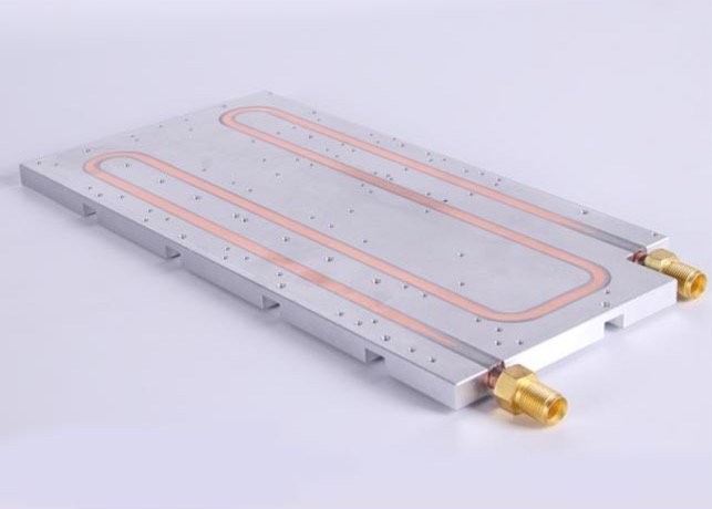
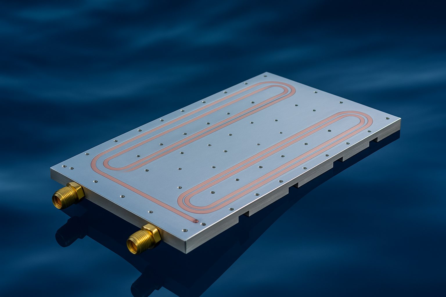
C-HH-01
Liquid Cold Plate
Coolant runs through channels machined into the plate; devices mount on the surface with thermal interface material.
| Heat flux | 200 W/cm² |
| Working pressure | 2.5 MPa |
| Temperature | −55 to +90 °C |

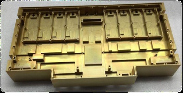
C-HH-02
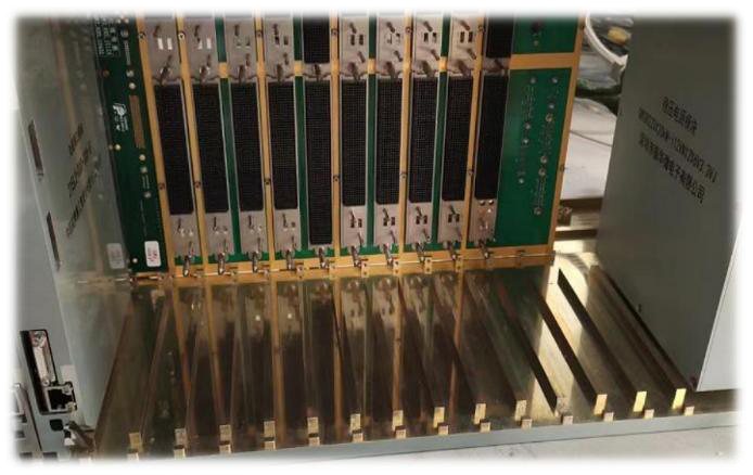
Liquid-Cooled Enclosure
Welded frame with internal coolant channels, built to ATR and MCU rugged formats with strong EMC shielding.
| Cooling | Side-wall, module or hybrid |
| Working pressure | 2.5 MPa |
| Modules | VITA or custom |
C-HH-03
Vapor Chamber
A vacuum cavity with a wick and working fluid spreads heat by evaporation and condensation.
| Equiv. conductivity | ≥ 3,000 W/m·K |
| Isothermality | ≤ 5 °C |
| Temperature | −45 to +80 °C |
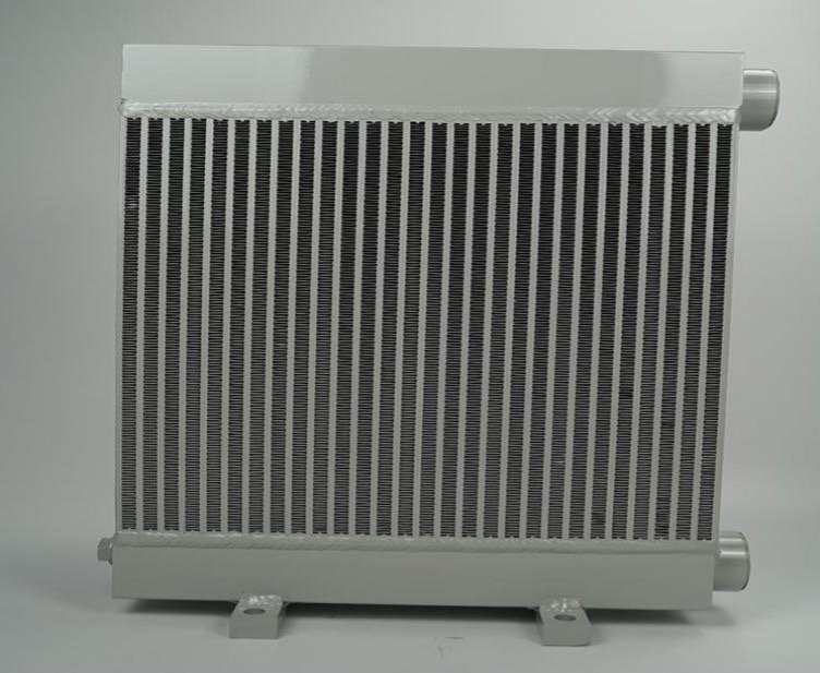
C-HH-04
Heat Exchanger
Multi-channel exchangers move heat between fluids, with optional coatings for marine and harsh duty.
| Media | Water, seawater, coolant, oil |
| Corrosion grade | C5-M |
| Capacity | Designed per requirement |
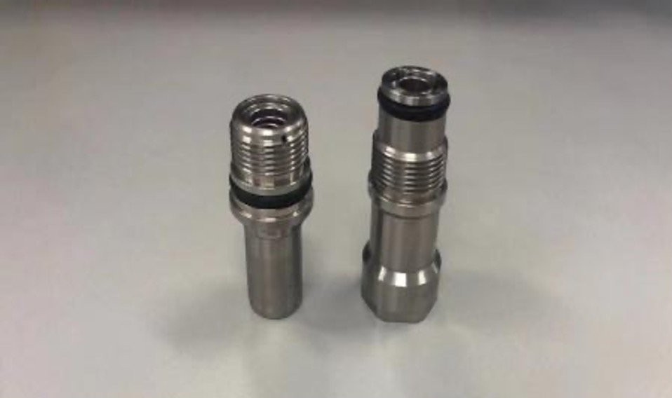
C-HH-05
Fluid Connector
Blind-mate, push-pull and bayonet versions that seal automatically when disconnected.
| Working pressure | 0–2 MPa |
| Sizes | DN3 – DN10 |
| Salt spray | 240 h |
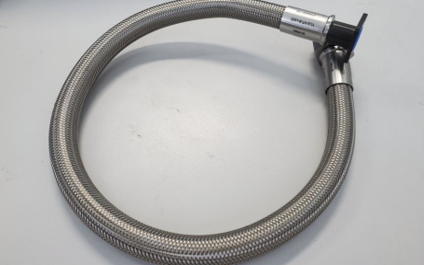
C-HH-06
Liquid Cooling Pipeline
PTFE hose with stainless braid for coolant, oil, fuel or gas, with flange or self-sealing ends.
| Working pressure | 0–35 MPa |
| Temperature | −70 to +260 °C |
| Sizes | DN8 – DN25 |
Vapor-chamber heat sinks
Same envelope. Cooler devices.
Thermal simulation against a conventional heat sink of identical size. Both designs: 6063 aluminum with acetone working fluid.
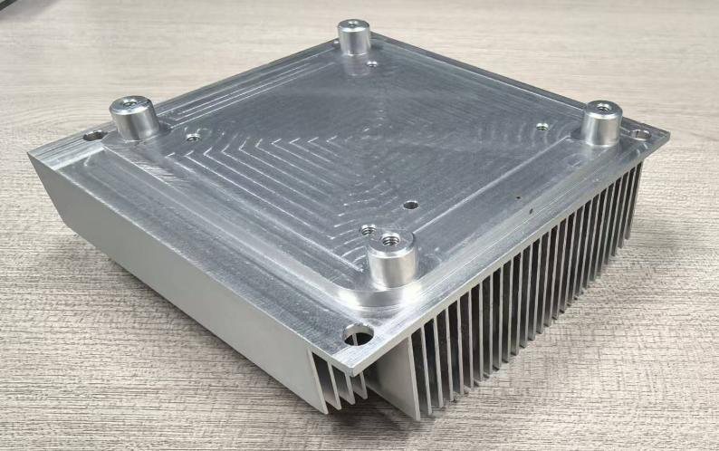
Case 01 · 4 × 50 W
200 W module heat sink
Simulated against a conventional heat sink of the same 100 × 90 × 28 mm envelope at 40 °C ambient.
| Conventional sink | 75.6 °C peak |
| Vapor chamber | 63.9 °C peak |
| Improvement | 11.7 °C cooler |
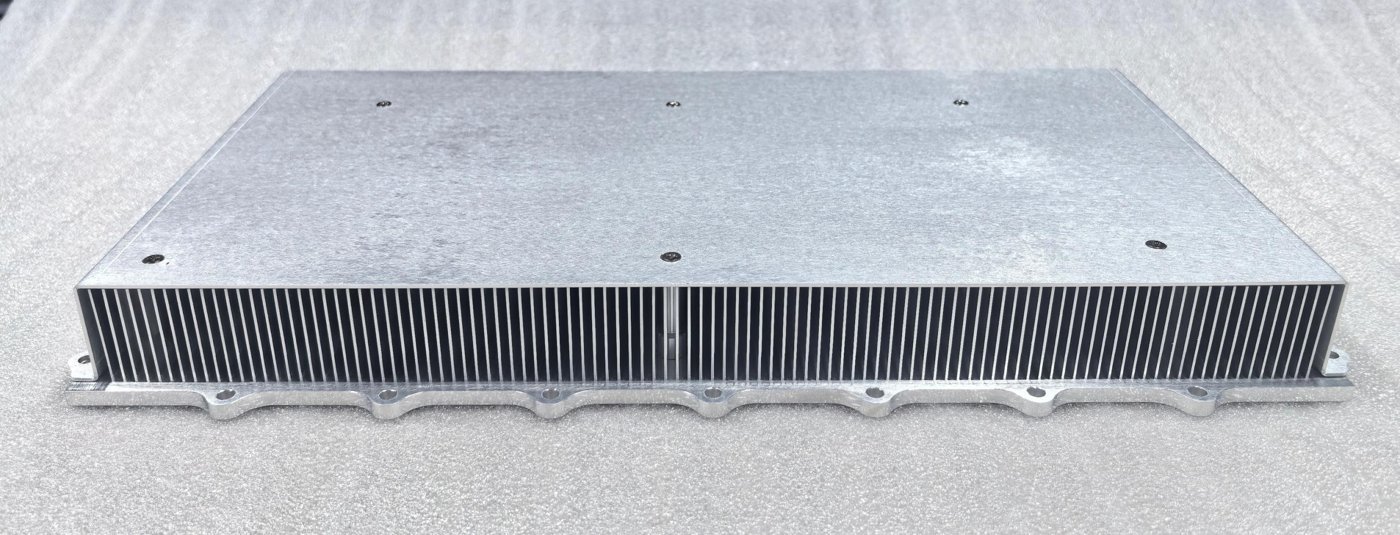
Case 02 · 6 × 660 W
3.96 kW power-stage heat sink
Simulated against a conventional heat sink of the same 300 × 200 × 40 mm envelope at 45 °C ambient.
| Conventional sink | 136.4 °C peak |
| Vapor chamber | 119.2 °C peak |
| Improvement | 17.2 °C cooler |
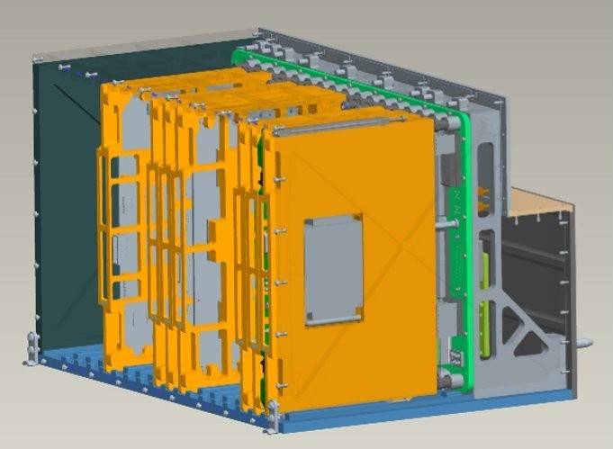
C-HH-02 · Liquid-cooled chassis
Coolant in the walls, modules in the slots.
Fluid channels run inside the welded frame. Heat leaves each module through conduction cold plates into liquid-cooled side walls — so one compact chassis cools a full stack of electronics.
- Side-wall liquid flow plus conduction cooling, or full module circulation
- Welded, sealed frame for vibration, corrosion and EMC shielding
- ATR and MCU rugged formats; VITA-standard or custom modules
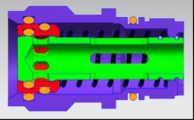
Inside a blind-mate connector
Plug in, pull out — no drips.
Both halves seal themselves, so modules mate and unmate without leaks. No locking mechanism to operate, low flow resistance, and radial float to absorb misalignment in a rack.
| Max working pressure | 1.6 MPa |
| Burst pressure | ≥ 2.5 MPa |
| Temperature | −40 to +70 °C |
| Mechanical life · material | 1,500 cycles · 316L |
Complete loops
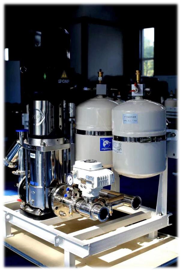
Water-cooling pump stations.
Pump, control valves and heat rejection delivered as one circulating system — matched to the cold plates and chassis it feeds.
01
Pump station
Circulation pumps and expansion tanks on a single frame.
02
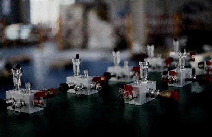
Control valve blocks
Valve blocks that route and regulate flow through the loop.
03
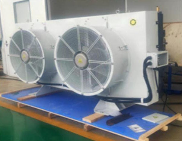
Radiator and fan unit
Liquid-to-air heat rejection that closes the loop.
Where it runs
Wherever electronics run hot and can’t fail.
Defense electronics
Radar, power supplies, transmitters and data processing.
Aerospace
Satellite radiators and phase-change thermal control.
Power electronics
Water-cooled IGBT modules for renewable-energy inverters.
Wind power
Converters, transformers, gearboxes and generators.
Data centers
Rack-level liquid cooling to lower PUE.
Send us your heat map.
Device power and footprint, allowable junction temperature, coolant, flow and envelope. We’ll simulate it and propose a cold plate, vapor chamber or full loop.